QUADRANT ANTENNA FOR SHORTWAVE RADIO BROADCASTING

GENERAL DESCRIPTION


photo quadrant antenna 
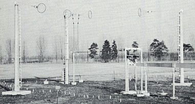
Omnidirectional transmitting antennas are most favoured when it is required to provide same time coverage of areas surrounding the transmitter site which extend up to 1300 km of radius, depending on the transmitter power.

If a single frequency operation is targeted to reach listeners day and night without retuning the receiver, a simple and therefor attractive design is the so-called quadrant antenna.

Similar to CCIR Regulations a special alpha-numeric code is used to describe quadrant antennas. In its most general form the antenna is denoted by HQ n/h, where:

H horizontal polarisation of the antenna
Q quadrant type
n the number of dipoles stacked vertically
h height of the lowest dipole above ground in wavelengths at the design frequency

Quadrant antennas consist of horizontal bent dipoles, the bent angle of which may vary from 60° to 90° with consideration of the required horizontal pattern characteristic (allowed deviation from perfect onmi pattern). It is obvious that simple dipoles cannot be operated over the entire shortwave broadcasting spectrum, although the "slenderness ratio", i.e. the ratio of dipole length to equivalent dipole diameter is selected for best broadband characteristics and the dipole is performed as an open multi-wire cage.

State-of-the-art design allows quadrant antennas to be operated over the frequency range, covering two adjacent frequency bands out of the shortwave broadcasting spectrum as defined by WARC '92 allocations under consideration of standard shortwave transmitter design.

This spectrum is spanned by:


Frequency
Band
fL in MHz fH in MHz
Frequency
Band
fL in MHz fH in MHz

6 5.90 6.20
15 15.10 15.80

7 7.10 7.35
17 17.48 17.90

9 9.40 9.90
19 18.90 19.02

11 11.60 12.10
21 21.45 21.85

13 13.57 13.87
26 25.67 26.10


Safety against corona effects, inadmissible heating and the VSWR capability over the selected frequency range of operation is ensured by choosing an appropriate wire diameter considering the mechanical forces due to wind and ice loads, span length and weight. Once the diameter of the wires is fixed, the number of wires forming the cage and the cage diameter itself are determined in a straight forward calculation.

The height of the lowest dipole above ground in wavelengths at the design frequency results from the choice of the vertical pattern characteristics as shown for a horizontal dipole in the plane of the bisecting line and may be used to give priority to distinct coverage areas. Moreover the graph shows that for near-range broadcasting, which requires high angle radiation the suspension height of the antenna above ground should be not higher than 0.4 λ and for reasons of the antenna gain not lower than 0.25 λ. If in addition, the effect of ground conductivity is considered, which may change with season we recommend a suspension height of 0.3 λ, in order to avoid the design of a ground screen.

picture vertical radiation pattern

In case two radio programs are to be transmitted simultaneously, two quadrant antennas are required and the mutual distance of these antennas should be not less than 150 m. (Note: diplex operation of one quadrant antenna only, is not recommended for a Standard design).

>From long-term operation of short-wave broadcasting stations, to near and medium range distances we can conclude that a quadrant antenna shall be seen as a perfect selection for the following reasons:

picture vertical/horizontal radiation pattern

Vertical and horizontal radiation pattern for lower and upper frequency band


(Description courteousy of Jürgen Reiche, Thomcast GmbH)

TYPICAL RADIATION PATTERNS
Azimuth pattern Elevation pattern
typical azimuth pattern quadrant antenna typical elevation pattern quadrant antenna


TYPICAL COVERAGE MAP
typical coverage map quadrant antenna


TECHNICAL SPECIFICATIONS
ELECTRICAL
Azimuth pattern omnidirectional
Frequency ranges 6-26 MHz, for two adjacent SW bands
Gain 7 dBi
Input impedance 300 ohm balanced
Polarization horizontal
Power ratings up to 500 kW carrier with 100% modulation
Specifications may change without notice

THIS TYPE OF ANTENNA IS AVAILABLE FROM
Manufacturer Type number Power Level
Ampegon Antenna Systems HQ

H
Transradio SenderSysteme Berlin HQ Series
M H