SLOPING V ANTENNA FOR SHORTWAVE RADIO BROADCASTING

GENERAL DESCRIPTION


The sloping V antenna is designed for medium range skywave circuits.

The antenna is directional and intended for use in the 8 to 30 MHz frequency band. Operation is extended down to 2 MHz with reduced performance.

The antenna is horizontally polarized for efficient performance over all types of soil and will handle up to 10 kW of power.

The antenna requires a minimum time and cost for installation and features low-maintenance components. Only a single support mast is required.

The sloping V antenna is fed with a balun that is usually located at the top of the mast in case of a coaxial transmission line or through an open wire feeder line.

The terminating resistors should be in the order of 300 ohm.
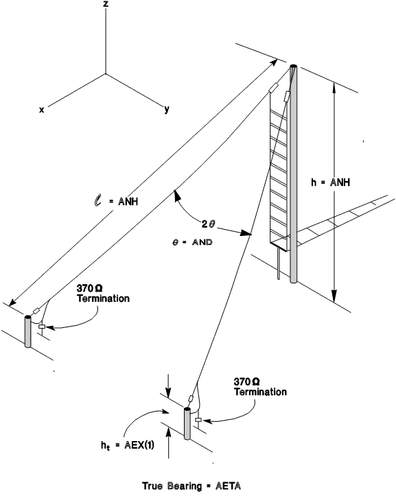
sloping V antenna


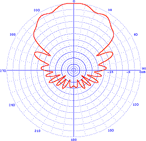
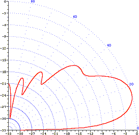
TYPICAL RADIATION PATTERNS
Azimuth pattern Elevation pattern
typical azimuth pattern sloping V antenna typical elevation pattern sloping V antenna


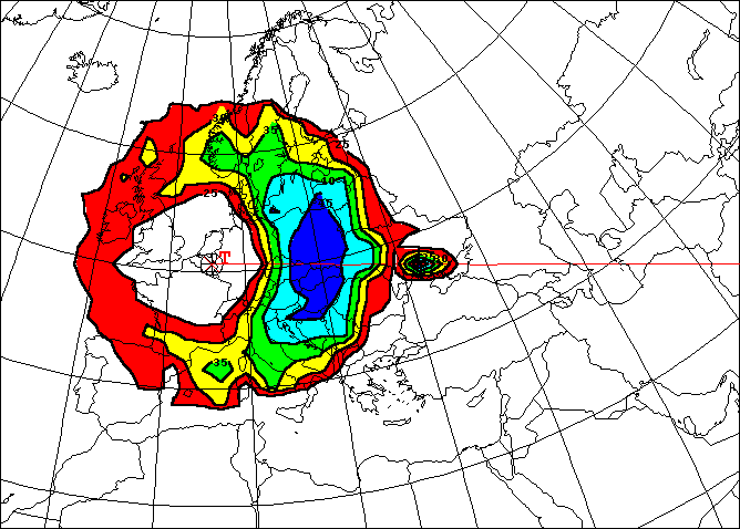
TYPICAL COVERAGE MAP
typical coverage map sloping V antenna


TECHNICAL SPECIFICATIONS
ELECTRICAL
Azimuth pattern directional
Frequency ranges 2-30 / 3-30 / 5-30 / 8-30 MHz
Gain 3 dBi
Input impedance 50 ohm unbalanced
Polarization horizontal
Power ratings 1 / 2.5 / 5 / 10 kW average
Specifications may change without notice

THIS TYPE OF ANTENNA IS AVAILABLE FROM
Manufacturer Type number Power Level
Antenna Products Corporation VH-830/L L M
RFS Radio Frequency Systems ANV Series L

ST Series L